Steel Structure Processing (II)–Basic Requirements
News 2022-06-14
For the processing, installation and acceptance of steel structures, in addition to the following requirements, the Code for Construction Quality Acceptance of Steel Structure Engineering shall also be satisfied. Before manufacturing and processing, the process documents and construction details shall be familiarized with, and the process preparation for each procedure shall be well done.
- Layout, Lofting and Marking-Off
(1)The format of the layout list shall be unified, and each batch of layout shall be assigned a serial number according to the project for easy reference.
(2)The layout list shall indicate the self-number of the steel plate, that is, the component number and part number correspond to the self-number of the steel plate to achieve traceability. During blanking, the steel plate number (self-number) specified in the layout list must be strictly followed. In case of any inconsistency, the blanking personnel shall promptly register and feedback to the Production Department for traceability.
(3)Blanking must be carried out strictly according to the layout. For the wing and web materials that need length splicing, gas shielded welding shall be used for backing and filling, and submerged arc automatic welding shall be used for surfacing. The following requirements must be met:
1)The spacing between the splicing seams of the flange plate and the web plate of the welded H-shaped steel should not be less than 200mm. The splicing length of the flange plate should not be less than 600mm; the splicing width of the web plate should not be less than 300mm, and the length should not be less than 600mm. The splicing welds shall comply with the requirements of Code for Construction Quality Acceptance of Steel Structure Engineering GB50205, and the weld quality grade is Grade I.
2)The splicing length of the side plates of box-shaped components should not be less than 600mm, and the spacing between the splicing seams of adjacent side plates should not be less than 200mm. The side plates should not be spliced in the width direction. When the width exceeds 2400mm and splicing is indeed required, the minimum splicing width should not be less than 1/4 of the plate width.
3)The component splicing welds shall comply with the requirements of the design documents. When the drawings do not specify Grade I welds, Grade II full-penetration equal-strength butt welds shall be adopted.
(4)For components with special requirements, a assembly diagram shall be prepared, which shall indicate the weld splicing position and the full-penetration and semi-penetration areas.
(5)For complex components and nodes, lofting shall be carried out before blanking. During blanking, the camber dimensions of various steel components, the shrinkage of various forms of welds and the blanking tolerance shall be fully considered to ensure that the dimensions of the front and rear processed components (accessories) are within the allowable error range specified in the Code for Construction Quality Acceptance of Steel Structure Engineering (GB50205-2020).
(6)Before marking-off, the marking-off personnel shall be familiar with the process requirements in the layout, and then carry out marking-off according to the layout diagram, blanking processing list, part sketch and computer real sample diagram prepared by the Production Department.
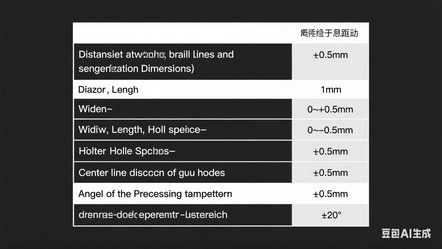
(7)The allowable deviations for lofting and templates are as shown in the following table:
Table 1-1 Allowable Deviations for Lofting and Templates
(8) During lofting, if omissions, errors in the construction drawings are found or if there is a need to modify the construction drawings for other reasons, the consent of the original design unit or the technician must be obtained, and no unauthorized modifications are allowed.
(9) During marking-off, if the material specifications or the appearance of the material quality do not meet the requirements, it must be reported to the material, quality, and technical departments for handling in a timely manner.
(10) For lofting and marking-off, the shrinkage allowance (including the shrinkage allowance of on-site welding) and the additional allowance required for cutting, milling ends, etc. shall be reserved. When marking-off, sampling shall be carried out in the direction specified by the process, and there shall be no punch marks or scratch defects on the outer side of the component. For high-rise steel frame columns, the elastic compression allowance shall also be reserved.
(11) After marking lines, the datum line, center line, and inspection control points shall be marked. Tools like chisels must not be used for marking. For a small number of prick punch marks, the depth shall not exceed 0.5mm, and there shall be no permanent marking traces on the steel plate.
(12) After the main plates and part plates are cut, the component number, part number, and size specifications shall be marked at the end. The parts of the same integral component should be placed together for subsequent assembly.
(13) During marking-off, the stress direction of the component should be made to be consistent with the rolling direction of the steel as much as possible. The steel used must be straight and free from damage and other defects; otherwise, it should be corrected or rejected first. When marking-off on steel plates, the rolled edges greater than 10mm shall be removed.
- Cutting and Milling Processing
(1) In principle, flame automatic cutting or numerical control (NC) cutting is used for cutting steel. Semi-automatic cutting is used for beveling. For parts in secondary positions where automatic or semi-automatic cutting cannot be used, manual cutting can be adopted. After cutting, the burrs, slag, and flash on the cutting edges shall be removed. For missing edges greater than 1mm, repair welding shall be carried out in a timely manner.
(2) After cutting is completed, clean the cut parts, self-inspect the quality of the cut parts. The inspection items and allowable deviations shall meet the requirements, and self-inspection records shall be made.
(3) After passing the inspection, mark the parts. The marking content includes: project name, part number, specification, material, steel plate heat lot number (or steel plate self-number). Marking position: 500mm from the end of the strip.
(4) After passing the special inspection, transfer to the next process.
(5) For cutting regular-shaped (rectangular) parts with a thickness > 12mm, semi-automatic flame cutting can be used. For parts of other shapes, NC cutting is preferred. For stiffening plates with a thickness ≤ 12mm, shearing can be used, but they must be straightened after shearing before use.
- Bevel Opening
(1) For short bevels (mainly for plate splicing, not for the assembly and welding of main welds), semi-automatic cutting machine with flame cutting is used. For long bevels (the four main welds of box girders), it is advisable to use an edge planer or a trackless self-guiding cutting machine for preparation.
(2) Except as required by the design, splicing with short materials is not allowed; otherwise, it can only be spliced after obtaining the design approval.
(3) Bevels for steel plate splicing and main welds of box girders.
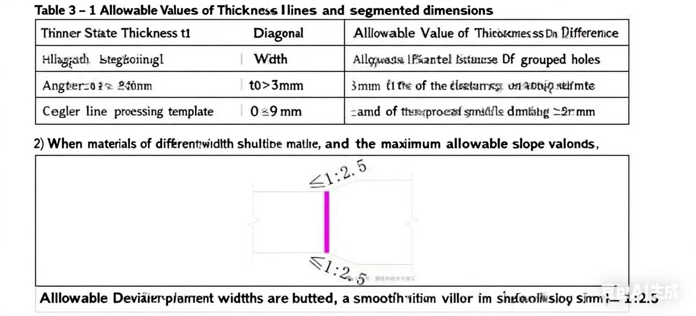
1. Groove forms for butting plates or pipes of different thicknesses
When butting plates or pipes of different thicknesses, if the thickness difference on one side does not exceed the allowable value, the weld shall be welded into a slope shape, and the maximum allowable value of the slope shall be 1:2.5. If the thickness difference on one side exceeds the allowable value, one or both sides of the thicker plate and the inner or outer wall of the pipe shall be processed into a slope before welding, and the maximum allowable value of the slope shall be 1:2.5. The allowable value of the thickness difference on one side is as shown in the following figure.
4. Straightening
(1) Materials entering the workshop for processing shall be flat without bending or deformation; otherwise, straightening shall be carried out. Straightening can be done by mechanical or flame straightening methods. The heating temperature for flame straightening shall be determined according to the steel properties, but shall not exceed 800℃. Water quenching is strictly prohibited for low-alloy steel materials. Heating straightening shall avoid the blue brittleness zone (200℃ – 400℃).
(2) The surface of the steel after straightening shall not have obvious concave surfaces and damages. The depth of scratches shall not be greater than 0.5mm, and shall not be greater than 1/2 of the negative allowable deviation of the steel thickness.
(3) Deformations of parts and components must be properly straightened before proceeding to the next process.
6. Stress Holes
(1) The size of the radius R of the weld access hole shall be larger than the width of the groove and meet the following requirements. Continuous welding shall be carried out at the weld access hole, as detailed below:
1. When the plate thickness T \leq 20 \, \text{mm} , the radius of the stress hole R = 35 \, \text{mm} .
2. When 20 \, \text{mm} < T < 40 \, \text{mm} , the radius of the stress hole R = 45 \, \text{mm} .
3. When the plate thickness T \geq 40 \, \text{mm} , the radius of the stress hole R = T + 10 .
(2) The specific size of the weld access hole shall be subject to the formal detailed drawings.
(3) For stiffening plates where stress holes are allowed to be manually made, standard templates must be used for marking lines, and cutting shall be done with a backing plate.
7. Hole Making
(1) If there are reserved holes in the steel beam, holes shall be made in the factory according to the dimensions and positions shown in the design drawings, and reinforcement shall be carried out in accordance with the relevant design requirements.
(2) Bolt holes must be made by drilling.
(3) The drilled holes shall be cylindrical and perpendicular to the plane of the steel. The perpendicularity deviation shall not be greater than 0.05t ( t is the thickness of the steel) and less than 1 \, \text{mm} . The deviation of the drilled hole diameter shall be 0 \sim + 0.5 \, \text{mm} . The edges of the holes shall be smooth and burr – free.
(4) Bolt holes shall be drilled at one time, and flame cutting is strictly prohibited. When the bolt diameter \leq 20 \, \text{mm} , the hole diameter is 1.5 \, \text{mm} larger than the bolt diameter; when the bolt diameter > 20 \, \text{mm} , the hole diameter is 2.0 \, \text{mm} larger than the bolt diameter.
(5) When processing holes with a radial drilling machine, the deviation of the marked hole positions shall be controlled within 0.5 \, \text{mm} . The center of the hole shall be marked with a prick punch and the size of the hole diameter shall be indicated. After marking the lines, the lines must be inspected and confirmed to be qualified before processing is allowed.
8. Bolts
(1) Ordinary Bolts: All ordinary bolts not specified in the design drawings shall adopt 4.6 – grade Class C bolts. The technical requirements for bolts, nuts and washers shall comply with the provisions of “Hexagon Head Bolts – Product Grade C” (GB/T 5780 – 2016), “Hexagon Nuts – Product Grade C” (GB/T 41 – 2016) and “Plain Washers – Product Grade C” (GB/T 95 – 2002).
(2) High – strength Bolts: 10.9 – grade torque – shear high – strength bolts with friction – type connections shall be adopted, and their performance shall meet the requirements of “High – strength Bolts with Torque – Shear Type for Steel Structures – Technical Conditions” (GB/T 3632 – GN/T 3633). The friction surfaces shall be treated by sand – blasting or shot – blasting, and no paint shall be applied. The design pre – stress of 10.9 – grade high – strength bolts shall meet the requirements of “Technical Specification for High – strength Bolt Connections in Steel Structures” (JGJ 82 – 2011).
9. Assembly
(1) Before assembly, the assembly workers must be familiar with the construction details, processing technology and other relevant technical requirements of this project, and check whether the part numbers, materials, dimensions, quantities and processing accuracies of the parts used for assembly meet the requirements of the drawings and technology. Assembly can be carried out only after confirmation.
(2) The platforms and jigs used for assembly shall meet the accuracy requirements of component assembly, and have sufficient strength and stiffness. They can be used only after inspection and acceptance.
(3) Components must be assembled in accordance with the technological process. Before assembly, rust, scale, oil stains and moisture within a range of 100mm on both sides of the weld shall be removed, and the metallic luster of the steel shall be exposed.
(4) Before welding, the welder shall check the quality of the assembly and surface cleaning of the welding parts. If it does not meet the requirements, it shall be repaired and welded until it is qualified before welding. When the assembly gap of the groove exceeds twice the thickness of the thinner plate or is greater than 20mm, it is not allowed to increase the length of the component or reduce the assembly gap by surfacing welding.
(5) After the components are assembled, self – inspection and mutual inspection shall be carried out, and finally submitted to the quality inspection personnel for inspection and acceptance. If any problems are found during the inspection, they shall be repaired and corrected in a timely manner.
(6) When fixtures are used for assembly, the base metal shall not be damaged when removing the fixtures; the remaining weld scars shall be ground smooth.
10. Splicing Requirements
(1) All components that need to be spliced shall adopt equal – strength splicing.
(2) Requirements for splicing of steel beams: Long materials shall be used for manufacturing as much as possible. When the net length of the beam is greater than the transportation unit, on – site splicing is allowed. The requirements for the splicing welds are detailed in the beam – column joint details and the following instructions. When the net length of the beam is less than or equal to the transportation unit, splicing of frame beams is not allowed, and splicing of secondary beams is allowed, but the number of spliced beams shall not exceed 50% of the total number of secondary beams. The splicing position shall be set at L/3 away from the support (L is the beam span).
(3) The splicing welds of steel beams shall adopt full – penetration welds. The welding process and the groove dimensions on the plates shall comply with the relevant provisions of the national standard “Code for Welding of Steel Structures” (GB 50661 – 2011).
(4) The splicing seams of the flanges and webs of the welded I – shaped (or H – shaped steel) cross – section shall be staggered, and avoid overlapping with the stiffeners. The distance between the web splicing seam and the parallel stiffener shall not be less than 200mm, and the distance between the web splicing seam and the upper and lower flange splicing seams shall not be less than 200mm.
11. Camber Requirements
When the length of the simply – supported steel beam is ≥ 8m, camber shall be set according to L/800; when the cantilever length of the cantilever beam is ≥ 4m, camber shall be set according to L/400.
 Scan the QR code and add WeChat